Introduction
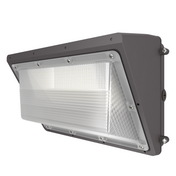
Parking lot lighting directly affects safety, security, customer experience, and operating costs. A properly installed LED area light — commonly called a “shoebox light” for its rectangular housing — delivers uniform, energy‑efficient illumination that meets IES RP‑20 standards, withstands harsh weather, and reliably operates for 50,000–100,000+ hours.
But buying high‑quality fixtures is only half the equation. Poor installation leads to flickering lights, premature driver failure, water ingress, liability from falling fixtures, and loss of DLC utility rebates that rely on proper documentation. This guide provides a comprehensive, professional‑grade installation workflow for LED shoebox lights in parking lots. Whether you are an electrical contractor, facility manager, or building owner, following these steps ensures a safe, code‑compliant, and long‑lasting installation in 2026.
Before You Start — Critical Pre‑Installation Steps
Step A: Finalize Your Lighting Design with a Photometric Plan
Do not begin installation without a professional photometric plan. Lighting design software such as AGi32 or DIALux EVO uses actual photometric data (IES files) to predict illuminance, uniformity, glare, and pole placement across your exact lot geometry. A photometric plan reveals:
-
Exactly how many fixtures you need — not a guess
-
Where poles should be placed (spacing‑to‑height ratio, typically 3:1 to 4:1)
-
Which distribution patterns to use (Type II vs. Type III)
-
Required lumens per fixture based on target foot‑candles
Most reputable lighting suppliers offer free photometric layouts with fixture purchase — always request one before ordering.
Step B: Verify Pole Foundations and Electrical Infrastructure
Inspect every pole location before installation. Base‑mounted poles for parking lots attach to concrete foundations using anchor bolts embedded during the concrete pour:
-
Anchor bolts must match the pole‘s base plate bolt pattern and are installed using a base template
-
Confirm concrete foundation depth (typically 3–6 ft depending on soil and pole height) and reinforcement
-
Verify that underground conduits (minimum 2‑inch) are clear and that pull strings are in place
-
Check that existing wiring and breaker panel capacity match the new fixture loads
Voltage verification: Most commercial LED parking lot lights operate on 100–277V AC. Confirm supply voltage matches fixture rating before connecting any power.
Step C: Gather Tools, Safety Equipment, and Fixture Components
Required tools:
-
Torque wrench with sockets (3/4″, 3/8″) — critical for meeting manufacturer torque specs
-
Allen wrench set (3/16″ and others)
-
Wire strippers, cutters, and weatherproof connectors
-
Voltage tester / multimeter
-
Screwdrivers (Phillips, flathead)
-
Drill and bits (for new mounting points)
-
Safety cables and clips
| Torque Reference for Common LED Shoebox Mounts | Value |
|---|---|
| Bracket to fixture (four A2/A3 screws) | 6.2 ft‑lbs / 8.3 Nm |
| Slip‑fitter set screws (four 3/8‑16) | 12 ft‑lbs |
Safety equipment:
-
Bucket truck, scissor lift, or boom lift (rated for height and weight)
-
Hard hat, safety glasses, high‑visibility vest
-
Fall arrest harness with lanyard and anchor sling
-
Insulated gloves
Fixture components to verify at ground level:
-
Correct mounting bracket (slip‑fitter, yoke, or direct arm)
-
Gaskets and weather seals
-
Hardware kit (bolts, washers, lock washers)
-
Photocell (if ordered) or NEMA receptacle and shorting cap
-
0‑10V dimming leads (purple +, gray −) if controls are planned
Installation Workflow — Step‑by‑Step from Pole to Power
The workflow assumes poles and concrete foundations are already in place and base‑mounted poles are secured.
Step 1: Prepare the LED Shoebox Fixture at Ground Level
Working at ground level is safer, faster, and reduces the risk of dropping hardware. Perform all assembly before lifting the fixture to the pole:
-
Inspect the fixture for shipping damage — cracked lenses, bent brackets, or loose components
-
Attach the mounting bracket to the fixture using the provided bolts. Torque to manufacturer specification: typically 6.2 ft‑lbs (8.3 Nm) for bracket‑to‑fixture bolts
-
If using a slip‑fitter (the most common mount for shoebox lights, designed for standard 2 3/8″ pole tenons), attach the slip‑fitter to the fixture now and leave the clamp bolts loose for on‑pole adjustment
-
Install the secondary safety cable (stainless steel cable with swage or crimped loops) through the fixture‘s dedicated anchor point
-
If the fixture includes a NEMA 3P receptacle (twist‑lock socket for photocontrol), ensure the socket is clean and the gasket is present
-
Set any field‑selectable DIP switches for wattage or CCT according to your photometric plan (most fixtures offer 100W/150W/200W selectable or 4000K/5000K selectable) — this is much easier at ground level than after mounting
Step 2: Mount the Fixture on the Pole
Raise the fixture to the pole using a boom lift or bucket truck with at least two workers — one to operate the lift, one to handle the fixture.
For slip‑fitter mounting (most common):
-
Slide the slip‑fitter over the pole tenon (2 3/8″ standard diameter)
-
Position the fixture at the desired height on the tenon (do not slide it to the very bottom — leave clearance for aiming adjustment)
-
Tighten slip‑fitter clamp bolts in a cross‑pattern using a torque wrench. For 3/8‑16 set screws, torque to 12 ft‑lbs
-
Attach the secondary safety cable to an independent anchor point on the pole (e.g., a welded eyelet or a cable wrapped tightly around the pole shaft below the mount). The secondary cable should be taut enough to catch the fixture if the primary mount fails, but with minimal slack. This is an OSHA safety requirement for overhead fixtures and is non‑negotiable.
For direct burial poles (pole shaft extends below grade and is anchored in concrete), the same slip‑fitter mounting applies at the top of the pole. However, direct burial poles must be properly specified to ensure adequate soil support — they simplify installation by eliminating anchor bolts and base plates but have specific structural requirements.
Step 3: Electrical Wiring — Line Voltage
⚠️ Never work on energized circuits. Verify power is off with a voltage tester, lock out the breaker, and tag it.
Most LED shoebox lights come with a short pigtail of wires (typically 6–12 inches). Connect them inside a weatherproof junction box (NEMA 4X or IP65 minimum). Use UL‑listed wire nuts or terminal blocks rated for wet locations.
| Wire Color | Function | Connection |
|---|---|---|
| Black / Brown | Line (120–277V) | Connect to building supply line |
| White / Blue | Neutral | Connect to building supply neutral |
| Green / Green‑Yellow | Ground | Connect to building supply ground (must be continuous back to panel) |
-
Grounding: The NEC requires the equipment‑grounding conductor to be run with the circuit conductors. Verify ground continuity from fixture all the way back to the panel.
-
Drip loop: Leave a service loop below the junction box entry so water does not wick into the electrical compartment.
-
For multi‑fixture circuits, respect NEC conductor sizing tables to prevent voltage drop — especially on long runs to remote poles.
Step 4: Controls Wiring — Photocell and 0‑10V Dimming (Optional)
Dusk‑to‑dawn photocell: Most parking lot LED shoebox lights are ordered with a NEMA 3P twist‑lock socket on top. Installation is simple — insert the photocell into the socket and twist clockwise to lock. Ensure the photocell sensor head is unobstructed and oriented toward the north (in the Northern Hemisphere) to avoid false triggering from vehicle headlights. If your lot uses a smarter NEMA 7P socket (with dimming lines), refer to the manufacturer‘s wiring diagram for 0‑10V control.
0‑10V dimming (bi‑level / motion sensor control): For energy‑sensitive parking lots, 0‑10V dimming is standard. This system uses two separate wire sets:
-
Line voltage wires (black, white, green) — power the fixture
-
Low‑voltage control wires (purple +, gray −) — carry the dimming signal (0 V = min dim, 10 V = full brightness)
Wiring 0‑10V:
-
Connect purple (+) and gray (−) from the fixture to the corresponding wires from the photocontrol or motion sensor
-
Polarity matters — purple must connect to purple/positive, gray to gray/negative
-
The NEC allows Class 2 low‑voltage wiring to be run without conduit in many cases, but verify with your local inspector
If not using dimming: Cap each dimming lead separately with a wire nut. Never tie the purple and gray leads together, and never connect them to ground — doing so will cause the fixture to malfunction or run at minimum output.
Step 5: Aim and Adjust the Fixture for Uniform Coverage
Aiming is critical. Even the most expensive LED shoebox light produces poor results if aimed incorrectly.
-
Use a digital inclinometer (smartphone app or dedicated tool) to set the tilt angle as specified in your photometric plan (typically 0° to 15° down from horizontal)
-
For rotation, sight along a straight edge of the fixture or use a laser pointer; align with reference markings on the lot (edge of pavement, centerline)
-
After aiming, tighten all locking bolts and re‑check tilt and rotation — movement often occurs during tightening
-
If the fixture has interchangeable optics (Type II vs. Type III lenses), verify the correct lens is installed per the photometric plan
Distribution pattern rules for parking lots:
-
Type II (narrow forward throw, up to 1:1.5 width‑to‑length ratio) — parking lanes, narrow roadways; use when spacing is 2–3× mounting height
-
Type III (wider forward throw, up to 1:2 ratio) — larger parking lots, perimeter installations
-
For standard parking lots with poles in driving lanes, Type II is correct. For perimeter‑mounted fixtures on building edges, Type III distributes light further into the space.
Step 6: Final Electrical Connections and Sealing
Once the fixture is mounted and aimed:
-
Make all final wire connections inside the weatherproof junction box
-
Use dielectric grease on all connections for coastal or high‑humidity locations
-
Secure the junction box cover with gasket — tighten evenly to avoid warping
-
Use weatherproof cable ties to secure loose cables, leaving drip loops below entry points
-
For conduit entries, use thread sealant and ensure no gaps
Step 7: Power On and Test
-
Remove lockout/tagout
-
Turn the circuit breaker on
-
Verify that all fixtures illuminate instantly — no flicker, no delay
-
If photocell equipped, cover the sensor head to simulate darkness — the light should turn on
-
For 0‑10V dimming, test low‑end dimming (10% output) and high‑end (100%) using a controller or sensor
-
Listen for unusual noise — buzz or hum indicates a wiring issue or driver incompatibility
-
If visible flicker occurs, the fixture may have a faulty driver or incompatible dimming control
Step 8: Night‑Time Photometric Verification (Recommended)
After all fixtures are installed and aimed, perform a night‑time verification:
-
Use a calibrated lux meter at the grid points specified in your photometric plan (typically a 20 ft × 20 ft grid, 3 ft above the pavement surface)
-
Measure horizontal illuminance and compare to design targets
-
If uniformity is poor or dark spots exist, re‑aim fixtures as needed
-
Some utilities require photometric verification documentation as part of rebate submission
Documentation for DLC V6.0 Utility Rebates (Critical 2026)
DLC certification is your gateway to utility rebates. In 2026, DLC SSL V6.0 became the active standard on January 5, 2026. V5.1 products will be fully delisted on December 15, 2026. Products listed only under V5.1 may lose rebate eligibility before your project is complete.
Documentation to capture during installation:
-
DLC certificate for each fixture model number — verify V6.0 listing before purchase
-
Fixture serial numbers recorded by pole location
-
Proof of purchase and installation date
-
Photometric plan (pre‑installation design)
-
Night‑time verification measurements (post‑installation)
-
Installation photos showing:
-
Secondary safety cables attached
-
Weatherproof junction boxes and conduit entries
-
Pole labels with serial numbers
-
-
Contractor information (licensed electrical contractor)
Most rebates require the exact fixture model number, DLC listing status, proof of purchase, and installation details. Some utilities offer higher incentives for DLC Premium products than for standard listed products, but rules and amounts vary.
Best practice for multi‑phase projects: Capture QPL listing evidence (screenshots or PDF exports) at submittal and at purchase — a “good“ SKU early in a multi‑phase project can become a “non‑qualifying“ SKU later if it was V5.1.
Safety Reminders for Parking Lot Lighting Installation
-
Work in pairs — never install fixtures at height alone
-
Use proper fall protection — full body harness attached to an independent anchor point (not the lift guardrail)
-
Never bypass lockout/tagout — verify power is off with a meter every time
-
Be aware of overhead power lines — maintain minimum approach distances
-
Weather hold — do not install during lightning, high winds, or heavy rain (wet poles and lifts increase electrocution risk)
-
Secure loose tools — dropped tools can kill
Common Installation Mistakes to Avoid
| Mistake | Consequence | Solution |
|---|---|---|
| No secondary safety cable | Fixture falls, causing injury or death | Always install independent secondary cable — non‑negotiable |
| Skipping photometric plan | Dark spots, glare, non‑compliance with IES RP‑20 | Always obtain AGi32/DIALux plan before ordering fixtures |
| Incorrect distribution type | Light spills off the lot or creates dark zones | Use Type II for parking lanes, Type III for large perimeter lots |
| Ignoring torque specs | Stripped bolts, loose fixture, or fall hazard | Use torque wrench — 6.2 ft‑lbs for bracket, 12 ft‑lbs for slip‑fitter set screws |
| Wiring 0‑10V leads together | Fixture runs at minimum dim or flickers | Cap each lead separately if not used — never tie together |
| Forgetting drip loops | Water wicks into junction box, causing driver failure | Leave service loop below entry point |
| No ground path verification | Electric shock hazard, driver failure | Verify continuity from fixture ground to panel |
| Photocell obstructed | Lights stay on during daylight — wasted energy | Position sensor head facing north, clear of building overhangs |
Post‑Installation Checklist
-
All fixtures mounted securely with primary and secondary safety cables
-
Slip‑fitter bolts torqued to manufacturer specification
-
Electrical connections made in weatherproof boxes — properly grounded
-
Drip loops present at all cable entry points
-
Aiming angles recorded and locked
-
Photocells correctly oriented and unobstructed
-
Night‑time photometric verification completed — meets IES RP‑20 targets
-
0‑10V dimming and controls tested (if applicable)
-
Serial numbers and installation photos documented
-
DLC V6.0 certificate saved and rebate application submitted
Frequently Asked Questions (FAQ)
Q: How high should LED shoebox lights be mounted in a parking lot?
A: For commercial parking lots, pole heights typically range from 15 ft to 40 ft. A 20‑foot pole typically pairs with 100–200W LED fixtures (13,000–32,000 lumens), while 30‑foot poles may require 200–300W fixtures (26,000–48,000 lumens). Higher poles require higher lumens per fixture but may reduce total fixture count.
Q: Can I install LED shoebox lights on existing metal halide poles?
A: Usually yes — LED shoebox lights are designed as direct replacements using standard slip‑fitter brackets on 2 3/8″ tenons. However, have a structural engineer review older poles (15+ years) for corrosion or fatigue, and recalculate wind loads — LEDs are lighter, which changes dynamic loading.
Q: What is the difference between Type II and Type III distribution for parking lots?
A: Type II produces a narrower rectangular pattern (up to 1:1.5 width‑to‑length) for parking lanes and narrow roadways. Type III produces a wider pattern (up to 1:2 ratio) for larger lots where fixtures are placed near one side. Choose based on your pole placement — Type II for fixtures in driving lanes, Type III for perimeter‑mounted fixtures.
Q: Do LED parking lot lights require a secondary safety cable?
A: Yes. OSHA requires secondary support for any overhead fixture that could fall onto personnel. Always install an independent safety cable from the fixture to an anchor point on the pole — never skip this step.
Q: Are LED shoebox lights eligible for DLC utility rebates in 2026?
A: Yes — if DLC V6.0 certified. V5.1 products will be fully delisted on December 15, 2026, and may lose rebate eligibility before your project is complete. Require DLC V6.0 listing in your spec for any incentive‑backed scope. Capture QPL listing evidence (screenshots or PDF exports) at submittal and at purchase. DLC Premium certified fixtures typically qualify for 300+ per fixture in rebates.
Q: How do I prevent water from getting into the junction box?
A: Use NEMA 4X or IP65 junction boxes with gasketed covers. Install drip loops (service loops below the cable entry point) so water drips off before reaching the seal. Apply dielectric grease to wire connections in coastal or high‑humidity areas. For conduit entries, use thread sealant and ensure no gaps.
Final Summary
Installing LED area lights (shoebox lights) in a parking lot is a systematic process that requires planning, precision, and adherence to safety codes. The eight‑step workflow:
-
Plan — obtain a photometric plan (AGi32/DIALux), verify poles and electrical infrastructure
-
Prepare — gather tools, safety gear, and assemble fixtures at ground level — torque bracket bolts to 6.2 ft‑lbs (8.3 Nm)
-
Mount — lift fixtures, secure slip‑fitter (torque set screws to 12 ft‑lbs) and secondary safety cable
-
Wire — connect line voltage (black/white/green) in weatherproof boxes; verify ground continuity
-
Control — install photocell in NEMA 3P socket; wire 0‑10V dimming leads (purple +, gray −) if used
-
Aim — use digital inclinometer to set tilt and rotation per photometric plan; verify Type II vs. Type III optics
-
Test — power on, verify instant operation, test photocell and dimming, check for flicker
-
Document — record serial numbers, capture installation photos, and submit DLC V6.0 rebate documentation
With a careful installation, your LED parking lot lighting will deliver 50,000–100,000+ hours of reliable, energy‑efficient illumination — meeting IES RP‑20 standards, eliminating maintenance for over a decade, and securing the utility rebates that shorten your payback period to 1–3 years.
Take action today: If your parking lot still relies on metal halide or HPS lighting, walk the lot at night, note the dark spots, and contact a qualified lighting professional for a free photometric design. DLC V6.0 is now active — and the V5.1 delisting deadline of December 15, 2026 means the time to specify compliant fixtures is now.